- 您现在的位置:买卖IC网 > Sheet目录2001 > ISL12082IUZ (Intersil)IC RTC I2C LO-POWER 10-MSOP
23
FN6731.3
November 24, 2008
the function will just be a matter of implementing software
and performing some calculations. Fairly accurate
temperature compensation can be implemented just by
using the crystal manufacturer’s specifications for the
turnover-temperature T0 and the drift coefficient (β). The
formula for calculating the oscillator adjustment necessary is
shown in Equation 9:
Once the temperature curve for a crystal is established, then
the designer should decide at what discrete temperatures
the compensation will change. Since drift is higher at
extreme temperatures, the compensation may not be
needed until the temperature is greater than +20°C from T0.
A sample curve of the ATR setting vs Frequency Adjustment
for the ISL12082 and a typical RTC crystal is given in
Figure 18. This curve may vary with different crystals, so it is
good practice to evaluate a given crystal in an ISL12082
circuit before establishing the adjustment values.
This curve is then used to figure what ATR and DTR settings
are used for compensation. The results would be placed in a
lookup table for the microcontroller to access.
Layout Considerations
The crystal input at X1 has a very high impedance, and
oscillator circuits operating at low frequencies such as
32.768kHz are known to pick up noise very easily if layout
precautions are not followed. Most instances of erratic
clocking or large accuracy errors can be traced to the
susceptibility of the oscillator circuit to interference from
adjacent high speed clock or data lines. Careful layout of the
RTC circuit will avoid noise pickup and insure accurate
clocking.
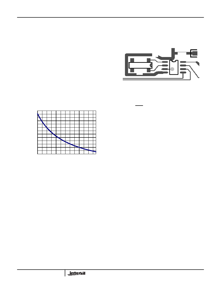
Figure 19 shows a suggested layout for the ISL12082 device
using a surface mount crystal. Two main precautions should
be followed:
1. Do not run the serial bus lines or any high speed logic
lines in the vicinity of the crystal. These logic level lines
can induce noise in the oscillator circuit to cause
misclocking.
2. Add a ground trace around the crystal with one end
terminated at the chip ground. This will provide
termination for emitted noise in the vicinity of the RTC
device.
In addition, it is a good idea to avoid a ground plane under
the X1 and X2 pins and the crystal, as this will affect the load
capacitance and therefore the oscillator accuracy of the
circuit. If the IRQ1/fOUT pin is used as a clock, it should be
routed away from the RTC device as well. The traces for the
VBAT and VCC pins can be treated as a ground, and should
be routed around the crystal.
Supercapacitor Backup
The ISL12082 device provides a VBAT pin which is used for
a battery backup input. A Supercapacitor can be used as an
alternative to a battery in cases where shorter backup times
are required. Since the battery backup supply current
required by the ISL12082 is extremely low, it is possible to
get months of backup operation using a Supercapacitor.
Typical capacitor values are a few F to 1F or more
depending on the application.
If backup is only needed for a few minutes, then a small
inexpensive electrolytic capacitor can be used. For extended
periods, a low leakage, high capacity Supercapacitor is the
best choice. These devices are available from such vendors
as Panasonic and Murata. The main specifications include
working voltage and leakage current. If the application is for
charging the capacitor from a +5V ±5% supply with a signal
diode, then the voltage on the capacitor can vary from ~4.5V
to slightly over 5.0V. A capacitor with a rated WV of 5.0V
may have a reduced lifetime if the supply voltage is slightly
high. The leakage current should be as small as possible.
For example, a Supercapacitor should be specified with
leakage of well below 1A. A standard electrolytic capacitor
with DC leakage current in the microamps will have a
severely shortened backup time.
Following are some examples with equations to assist with
calculating backup times and required capacitance for the
ISL12082 device. The backup supply current plays a major
part in these equations, and a typical value was chosen for
example purposes. For a robust design, a margin of 30%
should be included to cover supply current and capacitance
tolerances over the results of the calculations. Even more
Adjustment(ppm)
T
0
–
()2
=
β
(EQ. 9)
-400
-30
-20
-10
0
10
20
30
40
50
60
70
80
90
0
5
10 15 20 25 30 35 40 45 50 55 60
ATR SETTING
PP
M
ADJUSTME
N
T
FIGURE 18. ATR SETTING vs OSCILLATOR FREQUENCY
ADJUSTMENT
FIGURE 19. SUGGESTED LAYOUT FOR ISL12082 AND
CRYSTAL
U1
1
Y1
ISL12082
发布紧急采购,3分钟左右您将得到回复。
相关PDF资料
ISL1208IU8-TK
IC RTC/CALENDAR I2C 8-MSOP
ISL1209IU10-TK
IC RTC/CALENDAR I2C 10-MSOP
ISL1218IUZ
IC RTC LP BATT BACKED SRAM 8MSOP
ISL1219IUZ-T
IC RTC LP BATT BACK SRAM 10MSOP
ISL1220IUZ
IC RTC LP BATT BACK SRAM 10MSOP
ISL1221IUZ
IC RTC LP BATT BACK SRAM 10MSOP
ISL26134AVZ
IC ADC 24BIT SRL 80SPS 28TSSOP
ISL26319FVZ-T7A
IC ADC 12BIT SRL/SPI 16TSSOP
相关代理商/技术参数
ISL12082IUZ-T
功能描述:实时时钟 RTC W/RESEAL ALARM & TIMR FUNCTNS IN MSO RoHS:否 制造商:Microchip Technology 功能:Clock, Calendar. Alarm RTC 总线接口:I2C 日期格式:DW:DM:M:Y 时间格式:HH:MM:SS RTC 存储容量:64 B 电源电压-最大:5.5 V 电源电压-最小:1.8 V 最大工作温度:+ 85 C 最小工作温度: 安装风格:Through Hole 封装 / 箱体:PDIP-8 封装:Tube
ISL1208EVAL
功能描述:电源管理IC开发工具 EVALRD FOR ISL1208
RoHS:否 制造商:Maxim Integrated 产品:Evaluation Kits 类型:Battery Management 工具用于评估:MAX17710GB 输入电压: 输出电压:1.8 V
ISL1208IB8
功能描述:IC RTC/CALENDAR I2C 8-SOIC RoHS:否 类别:集成电路 (IC) >> 时钟/计时 - 实时时钟 系列:- 产品培训模块:Obsolescence Mitigation Program 标准包装:1 系列:- 类型:时钟/日历 特点:警报器,闰年,SRAM 存储容量:- 时间格式:HH:MM:SS(12/24 小时) 数据格式:YY-MM-DD-dd 接口:SPI 电源电压:2 V ~ 5.5 V 电压 - 电源,电池:- 工作温度:-40°C ~ 85°C 安装类型:表面贴装 封装/外壳:8-WDFN 裸露焊盘 供应商设备封装:8-TDFN EP 包装:管件
ISL1208IB8-TK
功能描述:IC RTC/CALENDAR I2C 8-SOIC RoHS:否 类别:集成电路 (IC) >> 时钟/计时 - 实时时钟 系列:- 产品培训模块:Obsolescence Mitigation Program 标准包装:1 系列:- 类型:时钟/日历 特点:警报器,闰年,SRAM 存储容量:- 时间格式:HH:MM:SS(12/24 小时) 数据格式:YY-MM-DD-dd 接口:SPI 电源电压:2 V ~ 5.5 V 电压 - 电源,电池:- 工作温度:-40°C ~ 85°C 安装类型:表面贴装 封装/外壳:8-WDFN 裸露焊盘 供应商设备封装:8-TDFN EP 包装:管件
ISL1208IB8Z
功能描述:实时时钟 I2C REAL TIME CLOCK/ CALENDAR 8LD RoHS:否 制造商:Microchip Technology 功能:Clock, Calendar. Alarm RTC 总线接口:I2C 日期格式:DW:DM:M:Y 时间格式:HH:MM:SS RTC 存储容量:64 B 电源电压-最大:5.5 V 电源电压-最小:1.8 V 最大工作温度:+ 85 C 最小工作温度: 安装风格:Through Hole 封装 / 箱体:PDIP-8 封装:Tube
ISL1208IB8ZR5291
功能描述:实时时钟 I2CAL TIME CLK/CLNDR ALL BATRY MODE TESTS RoHS:否 制造商:Microchip Technology 功能:Clock, Calendar. Alarm RTC 总线接口:I2C 日期格式:DW:DM:M:Y 时间格式:HH:MM:SS RTC 存储容量:64 B 电源电压-最大:5.5 V 电源电压-最小:1.8 V 最大工作温度:+ 85 C 最小工作温度: 安装风格:Through Hole 封装 / 箱体:PDIP-8 封装:Tube
ISL1208IB8Z-T7A
功能描述:实时时钟 I2CAL TIME CLK/CLNDR 8LD RoHS:否 制造商:Microchip Technology 功能:Clock, Calendar. Alarm RTC 总线接口:I2C 日期格式:DW:DM:M:Y 时间格式:HH:MM:SS RTC 存储容量:64 B 电源电压-最大:5.5 V 电源电压-最小:1.8 V 最大工作温度:+ 85 C 最小工作温度: 安装风格:Through Hole 封装 / 箱体:PDIP-8 封装:Tube
ISL1208IB8Z-TK
功能描述:实时时钟 I2C REAL TIME CLOCK/ CALENDAR 8LD RoHS:否 制造商:Microchip Technology 功能:Clock, Calendar. Alarm RTC 总线接口:I2C 日期格式:DW:DM:M:Y 时间格式:HH:MM:SS RTC 存储容量:64 B 电源电压-最大:5.5 V 电源电压-最小:1.8 V 最大工作温度:+ 85 C 最小工作温度: 安装风格:Through Hole 封装 / 箱体:PDIP-8 封装:Tube